¶ Overview
The Goal of this page is to outline the hardware aspects of a Barco E2 switching system as would be needed to design and specify a system utilizing an E2 system. Excluded from this page is software/setup direction for switcher operation beyond acheiving functioning I/O & processing.
the Barco EventMaster 2 system utilizes a slot based system, allowing a user to dynamically change the I/O capabilities of the system on an as needed basis. As a result, the Barco E2 system has no fixed I/O limitations. In Addition, multiple E2/S3/Ex Chassis can be linked together using the Link Expansion system, to increase I/O, and VPU processing power, to multiple chassis.
The E2 Chassis comes in two versions denoted as "Generation 1" and "Generation 2", the difference between the two chasis primarily focuses on I/O limitations on certain inbound card slots, as demonstrated in #card-slots
¶ Card Slots & I/O Resource Management
In both generation chassis, there are (In order of appearance, from left to right) 2 link expansion slots (denoted by yellow labels) 8 input card slots (blue), and 4 output card slots (green).
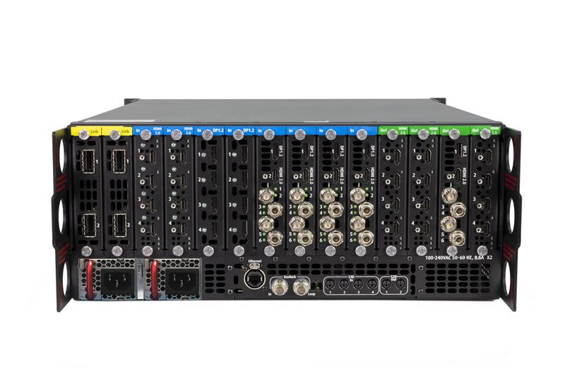
Any card slot is capable of holding any card of its type (input/output/expansion), however, the utilization of each card in the system can differ. Slot 14 (Furthest Right), is reserved for the multiviewer, when enabled (default), and when in multiviewer mode, can only be an HDMI 1.4/2.0 card.
Each card slot has a specific maximum bandwidth of signal it can carry, measured in "lanes" and often referred to as "port capacity". Port Capacities/Lanes start at 1L "Single Link", and increase to 2L "Dual link" and 4L "4K". In Generation 1 chassis, the firt 4 input card slots (slot 3-6), can carry a maximum of 4L into the system. All other slots are capable of carrying 8L. No such limitation exists in Generation 2 chassis.
Managing the number of lanes each card/slot is loaded with is imperitive to designing and spec'ing a Barco E2 based system, as bringing in higher resolution (2L/4L) signals on many cards will fill the cards total capacity, while some physical input connectors on the card may still be unused.
I/O cards carry similar lane count limitations, see table below for details.
this list is incomplete, lacks generation 1 cards:
| Card Name | Input/Output | Generation | Ports | Bandwidth |
|---|---|---|---|---|
| 4K60 Tri Combo In | INPUT | 2 | 1x DisplayPort 1.2 1x HDMI 2.0 4x 12G SDI |
8L |
| HDMI 2.0 Quad In | INPUT | 2 | 4x HDMI 2.0 | 8L |
| DisplayPort 1.2 Quad In | INPUT | 2 | 4x DisplayPort 1.2 | 8L |
| CXP I/O Card | INPUT/OUTPUT | 2 | 1x CXP | 8L |
| 4K 60 Tri Combo Out | OUTPUT | 2 | 1x DisplayPort 1.2 1x HDMI 2.0 4x 12G SDI |
8L |
| DisplayPort 1.2 Quad Out | OUTPUT | 2 | 4x DisplayPort 1.2 | 8L |
| HDMI 2.0 Quad Out | OUTPUT | 2 | 4x HDMI 2.0 | 8L |
| Fiber Output Card | OUTPUT | 2 | 2x SFP+ (SMPTE 297M) 12G | 8L |
¶ Generation 1 vs 2 Cards
Generation 1 cards are limited to 4L of bandwidth regardless of card slot. Generation 2 cards can carry up to 8L of bandwidth, chassis slot depending. Generation 2 cards additionally feature port mirroring and image rotation capabilities on output.
¶ CXP I/O Card
The CXP I/O card allows the use of an additional Barco EX chassis as a remote Multi I/O device for applications requiring distant I/O where otherwise long cables may be impractical or impossible. Note that the CXP I/O card must be installed in a respective Input or Output slot matching the card in use in the Ex chassis. Use of CXP I/O is expressly an alternative to using the Link Expansion system when the goal of expansion is to bring in remote I/O, as opposed to expanding the systems native maximum I/O, with reduced cable and engineering overhead versus using Link Expansion.
¶ Slot 14 - Multiviewer & Tally
When a multiviewer is desired, either a quad HDMI 1.4, or quad HDMI 2.0 card, must be installed in slot 14, additionally, the multiviewer function must be enabled on this slot (factory default). Using an HDMI 1.4 card, up to 2x 1080p multiviewer outputs can be acheived. Using an HDMI 2.0 card unlocks an additional 2x 1080P multiviewer heads, or a single 4K multiviewer head. Note that multiview heads will only run at either 1920x1080, or 3840x2160, no other aspect ratios or resolutions are possible. The use of an HDMI 2.0 card in the multiviewer slot additionally unlocks IP based tally functionality via TSL3.1 (as of sotware version X.X).
¶ Slot 1/2 - Link Expansion
The first two slots of an E2 chassis are occupied by Link Expansion cards, each featuring 2x 120G CXP I/O cards used for linking two or more E2/S3/Ex chassis, with some limiations.
I/O across a link expansion system is managed using "global links", the total number of which changes between configurations. Similar to port capacities on input/output slots, the number of inputs in the system may exceed the total global links capacity, as dual link/4K inputs will use up 2/4 global links each respectively.
¶ VPUs, Canvas Links, Layers, & Screen vs. Auxiliary Destinations
There are two types of outputs in an EventMaster system, screen destinations, and auxiliary destinations. Screen destinations allow for a full suite of processing, including multi output destinations with fades, data doubling, featering, layering, keying, etc. Aux destinations only allow hard cuts between individual inputs to a single output. While you can have an unlimited number of aux destinations (within limitations of available outputs), screen destinations are fixed to the number of canvas links, with each output port lane utilizing one canvas link.
Each E2 chassis has 9 VPU slots accessible from behind the front panel (one is only used on very early gen1 chassis, and was later deemed unessecary and has since remained unused), split into two banks of 4, "A" and "B". an E2 chassis must have at minimum 4 VPU cards in bank A to function. Chassis with only an A bank of cards is referred to as an E2 "Junior". Any junior can be upgraded to a full size E2 by installing the additional 4 VPU cards into bank B.
Each VPU bank carries 4x "Canvas Links" and 16x layers in a matrix. Any of the 4 VPU cards can allocate any of its 4 layers to any of the 4 canvas links automatically, based on parameters set by the operator. If more layers are required than a VPU bank can provide to a destination, the destination can use additional canvas links on the next VPU bank to afford itself additional layers.
When assigning layers to a desination, it is not only important to keep track of canvas links in use, but its also imperitive to understand the two different types of layers, and how/when one or another should be used. The first type of layer you can assign is a mix layer. Mix layers take up two VPU layers when assigned to a destination, and allow for seamless dissolving between any two sources within a layer. Single layers take up only one VPU layer when assigned to a destination, however, seamless disolving betweeen two sources is not possible, and therefore, this layer type is best suited only for layers that will always utilize cut transitions, or layers that will only be faded in/out of program.
¶ Latency
¶ Need To Adds
- bit depth
- custom EDID/port capacity calculation
- more detail on link expansion