Guides
- Guides
- 4 Output Mapping on ProPresenter With Decklink 8K Pro
- Binary, Decimal, and Hexadecimal
- Truck Packs
- Industry Best Practices
- Computer Networking
- Video Gems
- Genlock
- Dell EMC Isilon
- Sony CCU Connections - Intercom
Guides
Guides
We often come across things that are confusing or hard to set up, these are some guides on how to use specific gear or software, or more broad introductions to specific workflows and ideas prevalent in the industry.
Dell EMC
Genlock
Industry Best Practices
Sony CCU Connections
Video Hidden Gems
Truck Packs
ProPresenter
4 Output Mapping on Pro 7 + Decklink 8K Pro
4 Output Mapping on ProPresenter With Decklink 8K Pro
4 Output Mapping on ProPresenter + Decklink 8K Pro
Intro
Despite what Renewed Vision tells you, it is seemingly possible to output 4 simultaneous outputs to the Decklink 8K Pro. This is a tested method running the latest firmware (as of Sept 1, 2025), the latest version of ProPresenter, and the following configuration. The Decklink card is on an Apple Silicon Mac Mini, connected via a Sonnet Echo Express SE1 over Thunderbolt 3. It results in:
- 1 Audience Screen (1 Fill Output + 1 Key Output)
- 2 Stage Screen (formerly called Stage Display) Outputs
For the purposes of ease of use, the label my connectors A1-A4 for "Computer A". Remember the connections arranged on the spigots of the 8K Pro as: PCIE side Ref, 1, 3, 2, 4.
Decklink Configuration
- Output A1 (Ref Side) - A1 Key
- Set to: "SDI 1 In or Out"
- Output A3 - A3 StgScn 1
- Set to: “SDI 3 In or Out”
- Output A2 - A2 Fill
- Set to: “SDI 2 In or Out”
- Output A4 - A4 StgScn 2
- Set to: “SDI 4 In or Out”
ProPresenter Configuration
ProPresenter appears to prefer the KEY of the Key/Fill pair first.
- Create a new “Audience Screen”
- On the Hardware tab, select Output “Output A2 - A2 Fill”
- On the Alpha Key tab set to Alpa Type to “Premultiplied”
- Set the Output to “Output A1 (Ref Side) - A1 Key”
- Create 2 new “Stage Screen”s
- On the “Hardware” tab of each, set Output to “A3 StgScn 1”, and “A3 StgScn 2”, respectively


 Do for Stage Screen 1 and for Stage Screen 2 (not pictured)
Binary, Decimal, and Hexadecimal
Binary, Decimal, and Hexadecimal
Overview
Binary, Decimal, and Hexadecimal are all different means of representing numbers. The different types are used depending on the level of abstraction when it comes to computational hardware and each type has its place.
Decimal
Decimal is the "standard" nomenclature of representing a number. Officially, it is called base 10 and typically will be abreviated with a subscript 10 at the end of the number when presented alongside binary or hexadecimal values, however some sources choose to ignore the subscript for base 10 only. The reason it is called base 10 is because each digit has 10 distinct values (0-9).
Examples
810
12410
204810
Binary
Binary is a way of representing numbers in base 2 (two), where each digit can have two values (0, 1). Binary is typically used close to hardware where a 0 can be representing by one voltage and a 1 can be represented by another voltage, however different encoding schemes exist where 0s and 1s could be decoded from the phase of a signal, frequency of a signal, voltage transfer over a single bit period of a signal, etc. Regardless, once it is converted to binary it can represent data and numbers in a logical form. When written, it is convention that the right-most digit (or bit) represents the least significant value (typically 0/1). Sometimes underscores are appened in between groups of 4 or 8 bits for readability (similar to commas in decimal notation). Each bit represents 2 to the power of the position of that bit from right to left, starting with 0. A collection of 8 bits is called a byte.
Examples
Bits value table
| Bit Position | 8 | 7 | 6 | 5 | 4 | 3 | 2 | 1 | 0 |
|---|---|---|---|---|---|---|---|---|---|
| Value | 2^8^ | 2^7^ | 2^6^ | 2^5^ | 2^4^ | 2^3^ | 2^2^ | 2^1^ | 2^0^ |
| Decimal | 256 | 128 | 64 | 32 | 16 | 8 | 4 | 2 | 1 |
Binary and Decimal numbers
10002 = 810
0111_11002 = 12410
1000_0000_00002 = 204810
Converting from Decimal
To go to binary from decimal, find the largest power of 2 which can fit into the signal, add a 1 in the position of that value, then subtract that value from the decimal number. Continuously repeat this while adding 0s to the signal to pad values which cannot fit into the remainder.
Example
| Step | Current Decimal Remainder | Step | Current Binary Value |
|---|---|---|---|
| 0 | 86 | -64 | 1000000 |
| 1 | 22 | -16 | 1010000 |
| 2 | 6 | -4 | 1010100 |
| 3 | 2 | -2 | 1010110 |
| 3 | 0 | -0 | 1010110 |
Converting to Decimal
To convert from binary to decimal, multiply each value with a 1 in it with it's position's weight and sum the weights
| Bit Position | 6 | 5 | 4 | 3 | 2 | 1 | 0 |
|---|---|---|---|---|---|---|---|
| Value | 1 | 0 | 1 | 0 | 1 | 1 | 0 |
| Weight | 64 | 0 | 16 | 0 | 4 | 2 | 0 |
| Sum: 64 + 16 + 4 + 2 = 86 |
Hexadecimal
Hexadecimal (often abbreviated as Hex) is effectively only used as a human-readable format of binary. It is base-16 which allows for four digits in binary to be represented as 1 digit in hexadecimal. It is often used when representing long binary numbers in a display for a human to read. Each byte can be represented as 2 digits in Hex. Hex numbers can either be noted by having the subscript 16 after, or by being prefaced with "0x". Since decimal only offers digits 0-9, hexadecimal represents the remaining 6 digits with letters A-F. A table is attached below to show the correlation.
| Hex Value | Decimal Value | Binary Value |
|---|---|---|
| 0 | 0 | 0000 |
| 1 | 1 | 0001 |
| 2 | 2 | 0010 |
| 3 | 3 | 0011 |
| 4 | 4 | 0100 |
| 5 | 5 | 0101 |
| 6 | 6 | 0110 |
| 7 | 7 | 0111 |
| 8 | 8 | 1000 |
| 9 | 9 | 1001 |
| A | 10 | 1010 |
| B | 11 | 1011 |
| C | 12 | 1100 |
| D | 13 | 1101 |
| E | 14 | 1110 |
| F | 15 | 1111 |
Examples
| Decimal Value | Binary Value | Hex Value |
|---|---|---|
| 56 | 0011_1000 | 0x38 |
| 12 | 0000_1100 | 0x0C |
| 15 | 0000_1111 | 0x0F |
Negative Numbers
Overview
Negative numbers are represented in binary in either two different ways: a sign bit, or 2's complement.
Sign Bit
A sign bit is when a specific bit of the value is assigned to represent the sign, often with a 0 representing positive and 1 representing negative. Typically the sign bit is the most significant bit (MSB). This was one of the first ways to represent negative numbers in binary, and has flaws as it makes computation such as addition and subtraction harder to do in hardware, and implements two different 0 values, a positive and negative (+0 / -0).
Examples
| Decimal Value | Binary Value |
|---|---|
| 0 | 0000_0000 OR 1000_0000 |
| 12 | 0000_1100 |
| -12 | 1000_1100 |
2's Complement
Two's complement is the more unanimous method for representing binary numbers. In order to represent a negative number in binary, take the positive number in binary, flip all of the bits, and add 1. Reversing the process to convert a negative to a positive is just a matter of doing the same process of flipping all the bits and adding 1. To check if a number is positive or negative, the most significant bit can be checked for being a 1 (negative) or 0 (positive). This format is popular because it maintains having only one 0 value, and allows direct computation using the same circutry as normal, positive binary numbers.
Examples
| Deicmal Value | Binary Value |
|---|---|
| 0 | 0000_0000 |
| 12 | 0000_1100 |
| -12 | 1111_0100 |
Truck Packs
How to Pack Road Cases Into Transportation
Preface
In this guide we will first go over the standardized dimensions of trucks in North America & Europe. We will then cover the standard sizes of roadcase used, and finally, we will cover how to correctly pack all of this into a standardized truck.
Standard Truck Sizes
In North America, there are 3 common sizes of truck trailer you will most encounter. While other sizes are possible and do exist, these are the most common sizes transportation companies and truck rental providers have all standardized around, and as such, will be the primary focus of this guide.
16'
often also referred to as a 3 ton
These trucks commonly do not require specialty/commercial drivers licenses, and as a result, typically have a significantly lower weight limit. They are popular for the smallest of shows, and day to day item transfer, but can be inconvenient to use on site as a result of their small size.
26'
often also referred to as a 5 ton
While both the same dimension, these trucks are commonly available in two different versions from most major transport rental providers. As licensing of vehicles is most often limited by weight, these trucks are often available at a lower GVWR (gross vehicle weight rating) for non speciality/commercial license holders to be able to drive. It should be noted that trucks in such state are very easy to load overweight, and should be used very catiously. The second and more common option available is this same truck with its full factory certified GVWR. These versions often require specialty/commercial licensing, depending on your region.
Semi
often also referred to as just a "trailer"
 dimensions shown as interior
Standardizing Load Sizes
All road cases should be measured from the absolute edges, including the outside of the balled corners, if present.
Standard Case Heights
In all case dimensions, standard road cases typically run 24" tall, not including the casters. Some companies will also inventory "high top" versions of their 48" x 24" cases, typically 32" tall, which are normally reserved for use on items that are already tall in nature, where needing to reach the bottom of the case is less important.
48" x 32"
often also referred to as a "cadillac"
48" x 24"
often also referred to as a "standard", "half pack", or "48"
32" x 24"
often also referred to as a "third pack", or "32"
24" x 24"
often also referred to as a "quarter pack", "half-standard", "24", or "MUT" (abbreviated 'multi use trunk')
24 x 12"
How to Load A Truck
Correctly loading a truck is crucial to the speed at which a show will be able to load in/out, how many trucks will be needed, and the ultimate safety when the truck is in motion. It is important to note that in North America, the driver of a truck typically has a legal responsibility to know what their hauling, and to ensure the load is safely secured. Ultimately, the driver of the truck always has the final say on how the truck will be packed, but this guide outlines some suggestions and best practises that can help educate this process.
Weight Distribution
Crucial to the safety of a truck is how the load is distributed throughout the trailer. Trucks are most stable when the heaviest section is closest to the driver, and handling is most predictable when the weight on either side of the trailer is relatively even. Take time to ensure that when loading a truck the heavier items are not all on the left or right side, a 50/50 mix down each side is best. When stacking items, its important to remember that not all locations may have access to forklifts, and as such, care should be taken to ensure any cases stacked ontop of another should be lighter, the heaviest of cases should be left to the bottom of the stack always to prevent uneccesary human lifting.
Order of Items
One of the biggest markers of a good truck pack is the order in which the truck has been packed. Analyzing the flow of a typical production, the first thing that happens on site is the rigging team begins attaching motors to their designated points in the ceiling. Shortly following this, audio attaches their PA, video attaches LED walls, and LX positions their trussing. An efficient truck pack will keep this in mind, and will pack rigging hardware and motors closest to the door, allowing first access to whats first needed on the show floor. Closer to the back of the truck you'd find specialty scenic, lighting ground packages, staging, cameras, and similar gear that typically wouldn't be installed until after other major processes, such as points taking to trim, have already taken place. This concept should also extend more broadly when planning a multi-trailer pack. While it may be tempting to designate one truck to audio, one to video, one to lighting, one to miscellaneous staging/rigging/scenic, consider that not all venues have the infrastructure to have all trailers docked and open at the same time, a more logical approach to something like this may be the first trailer containing rigging, lighting pre-rig, and line arrays, while the second trailer contains non pre-rig truss, led wall, and flown soft goods. Only on the later trailers would you begin to hold technical racks, consoles, lighting ground packages, cameras, staging, ground scenic, etc. An important addendum to this, is worktrunks, tool chests, and communications tools such as two way radios, these items should always be the absolute first thing off of trucks, and should always be the absolute last thing on trucks, as these will contain items neccesary to safely commence the load-in/out, such as diagrams/plots, tools, PPE, first aid, and communications equipment.
Non Standard Cases
To-Do
- add lots of pictures
- clarify the hecc out of this when its not 5am
Industry Best Practices
Industry Best Practices
Document your work.
Backup early, backup often, backup multiple places.
Always have an exit plan. How do I recover from whatever I am doing if it doesn’t go to plan?
Always double check you're recording. If possible have a backup record. (As an excercise, consider how much it would cost / how much work it would take to re-create the program/performance if the record didn't happen or the record failed... it quickly becomes obvious it's worth a second glance to confirm).
Keep a copy of the previous software when upgrading. If possible archive every version– you never know when you need to roll back to support a device with incompatibiltes.
Follow proper cable wrapping techniques to prevent damage to your cables and ensure they are properly organized.
Learn what hardward / software is standard in the industry where you work and try to get hands on experience.
Follow proper safety procedures when working with electrical and electronic equipment. This includes wearing protective gear, following proper lifting techniques, and knowing how to properly handle and use tools and equipment.
Know how to use your equipment's diagnostic and monitoring tools. This will help you troubleshoot problems and identify potential issues before they become major issues.
Industry
This business is about relationships and it's a smaller industry than you think. Talk to people and make connections. Work hard in maintaining those relationships—those relationships are the way you get work.
Never burn a bridge.
Be confident in what you know, but also realize there are other people who know a lot too, so don’t get discouraged or annoyed when they actually do know more than you. On the flip side, don’t get annoyed when someone doesn’t know as much as you do, and don’t be condescending or rude when explaining something, even if in your mind it’s “basic”.
Learning the way something is done now and sticking to that one way is dangerous, innovation is job security.
At the end of the day; it's not about the gear, it's about the product.
Don't be afraid to say you don't know something because it is painfully obvious when someone is faking it when it comes to the niche broadcast stuff.
Reading the manuals puts you ahead of 70% of folks (sometimes this includes the folks who work for the company who made the product).
Video
Use 75 Ohm cables & BNC barrels for SDI.
When possible, genlock everything.
If using Blackmagic Design equipment, budget enough to buy a second unit for when the first one burns up. 🔥
System Adminstration
Always reboot servers and workstations between installs/uninstalls/upgrades/patches/firmware.
Have a control of your updates / update cycles. The worst thing that could happen is a machine updating during a show or while on-air.
If possible avoid joining mission critical workstations to the domain (incase a DC doesn’t load/boot). If you can't avoid, make sure you have a local admin account.
Don’t make more than one large change at once to make rollback easier to determine.
Try to keep your devices at fixed IP addressing. Either set the IP statically or use a reservervation on your DHCP server.
Test your network cables. When possible certify them.
Don't mix your production protocols on the same VLAN. Seperate core services onto their own VLANs (ie Dante, NDI, ARTNET should all exist on their own network VLAN)
Audio
Learn proper cable wrapping technique.
Do appropreate gain staging and leave headroom.
Invest in a good head amp.
It's recommended that phantom power be turned off when using ribbon microphones.
Computer Networking
Computer Networking
Resources
Visual Subnet Calculator: https://www.davidc.net/sites/default/subnets/subnets.html
Overview
Premise
This guide is not designed to be all-encompassing nor a replacement for professional learning. This guide is purely to help describe overall concepts in TCP/IP networks and serve as a basis for further independent learning.
Traffic Types
A single packet of information on a network has three different means of communicating across that network: Unicast, Broadcast, and Multicast
Unicast
Unicast traffic is any traffic sent from one source to one destination and no other destinations receive the message.
Broadcast
Broadcast traffic is unlike unicast traffic as a single source will send a packet which is received by every device in the network. Broadcast packets should be used sparingly and with small payloads in order to minimize the impact that they have on the network as having too many unnecessary broadcast packets can flood a network with traffic and saturate the link speed across the network, effectively bringing the network to a crawl in terms of speed and latency. Broadcast packets are sent by setting either or both the IP address to 255.255.255.255 or MAC address to FFFF::FFFF (all F). As such, the top-most IP address of a subnet (x.x.x.255) is reserved for broadcast traffic and should not be assigned to devices.
Multicast
Multicast is a derrivative of broadcast as it allows one or more sources to send traffic to one or more destinations. Multicast is defined by the Internet Group Management Protocol or IGMP and is the most complex of the different means of sending traffic over the network and requires special configuration. The synopsis of multicast is that receiving devices inform the network that they want to listen to a specific multicast IP address, then senders can transmit data to that reserved IP address and it is received by the receivers. This requires careful configuration of the IGMP Querier and IGMP Snooping. The querier will periodically quiery devices to see what multicast traffic they are interested in receiving. IGMP snooping on switches will allow switches to read those packets to view the membership reports generated by the receivers so that they know what traffic to forward to them and what traffic to not. If the querier's interval is higher than the switches' IGMP snooping timeout interval, then the switches will stop sending traffic to receivers for a period until the querier re-establishes what the receivers are interested in listening to.
In the event IGMP snooping is disabled, multicast traffic will be forwarded as broadcast traffic by switches, which in video over IP or similarly high bandwidth workflows can cripple networks.
Multicast traffic is organized by desination IP address utilizing the set-aside range of 224.0.0.0 to 239.255.255.255 IPv4 addresses, however some addresses are reserved for IGMP management of the streams so referencing documentation prior to assigning transmit and receive IP addresses on devices is important.
OSI / TCP/IP Models
Overview
The foundation of modern computer networks is derrived from the OSI and TCP/IP models. These models were developed to help describe how computer networks operate on a logical level where changes can be made within any level of the models without affecting other levels. For example, say a new standard for how to transmit data over a new medium becomes available, it would only necessitate adaptions in layer 1 without requiring changes at other layers (usually).
The OSI model is generally described as 7 layers enumerated 1 through 7 while the TCP/IP model is generally either 4 or 5 layers. Both models are applicable for different applications, however when it comes to network design there is a seemingly standardized understanding of the layers and how they relate to a network as described below:
| Layer | Name / Description | Examples |
|---|---|---|
| 4 | Transport Layer | TCP, UDP, Ports, Firewalls |
| 3 | Network Layer | IP Addresses, Routing, Subnets |
| 2 | Data Link Layer | MAC Addresses, Switching, VLANs |
| 1 | Physical Layer | Fiber, Twisted Pair, Coax, Encoding schemes |
This descibed terminology is often used by manufacturers for marketing. A layer 3 switch for example is a standard ethernet switch which operates on layer 2, but contains layer 3 features such as routing between networks / subnets.
Layer 1 - Physical
The physical layer is responsible for how the data gets from one location to another. This means that the mediums themselves that the data is transported by and the encoding schemes used on those mediums are included within this layer. Generally speaking, modern high-speed networks rely primarily on using twisted pair cable, such as CAT-6, CAT-6A, etc. and fiber optics (either multimode or singlemode) for the core of the network. Historically, coaxial cable (for example DSL lines) has been used and is included in this layer, alongside other more specialized or experimental mediums such as laser communications between satellites.
Wireless devices such as those implementing Wi-Fi and wireless point-to-point links can technically be included in this layer, however those devices tend to spread into layer 2, so it is not entirely accurate to claim that they are encompassed entirely within the physical layer.
Most items within this layer are commonly-known and are easily researchable so this guide will not go in-depth into the physical layer, but the key take away is to know the limitations of each common modern medium that is used, such as distance limitations with twisted pair cable, or cost limitations with fiber optics including transceiver modules.
Layer 2 - Data Link
The data link layer is where Ethernet packets are formed and live. Each unit of infromation transmitted over the network is separated into one or more packets and then sent. Each packet has a header which has information on how to get the packet from its source to its destination, followed by the payload which is the raw data that is being sent.
Each endpoint device has a MAC address assigned to its interface, either manually or more typically directly from the manufacturer of the interface. Each packet then contains a source and destination MAC address within its header which helps to inform the network on where to send the packet, and tells the receiving device where the packet came from. Switches will read the header of a packet, then reference a table it has stored in its memory of what MAC addresses are on which port of the switch, then will send the packet out the port that corresponds to the destination MAC address. In the event that the switch does not have an entry in its MAC address table, the swtich will send the packet out of all ports in a process known as "flooding." In this way, the packet becomes broadcast rather than multicast.
Address Resolution Protocol (ARP) is commonly used on the layer 2 network in order for endpoint devices to find out the MAC address of a destination they want to reach. The simplified way it works is that a sender will send a broadcast packet out to the network asking which device has a certain IP address. Devices that receive the packet which do not have that IP address simply forget about the packet and do not respond. In the event that a device does correspond to that IP address, it will send a unicast response to the sender of the original packet stating its own MAC address. The sender will then cache the MAC address into its own MAC address table, so that whenever it needs to send data to that same IP address it can reference that table without sending another ARP packet. The entire conversation is also being listened two by the switches which take notice on the source addresses within the packets and record them alongside the port they arrived on in its own MAC address table, so that further communication to those devices can be done over unicast.
VLANs, or Virtual Local Area Networks, also live on layer 2. These are specified by the IEEE 802.1Q standard and as such are also referenced as dot1q. VLANs work as a means of separating traffic by effectively creating separate network topologies per VLAN whilst using the same hardware. For example, a single switch could have half of its ports on one VLAN while the other half are on a second VLAN. When a broadcast packet arrives at the switch, it will only be forwarded to the ports which are also assigned to the VLAN. This allows multicast and broadcast traffic to be separated between different devices. In the video engineering world, it is a good practice to separate different kinds of devices onto different VLANs. This way if a manufacturer uses an odd protocol or incorrectly implements the Ethernet protocol which results in significant broadcast traffic being sent, it minimizes which devices are forced to listen to those packets, freeing up bandwidth for those devices and potentially fixing other problems.
Layer 3 - Network
Layer 3 generally deals with IP addresses, subnets, and routing between different subnets. Like every device has a MAC address, they generally also have an IP address. Unlike with MAC addresses, IP addresses are typically assigned over the network by a DHCP server, however they can also be assigned manually directly on the device.
Subnets are used to separate traffic logically by dividing IP addresses into ranges of IP addresses. A subnet is also called a network as traffic cannot pass from one subnet to another without the need of a router to interconnect the two networks, however this can get confusing as the term network is also used to refer to overarching communications systems involving multiple subnets. A subnet is defined in two parts: the address and the mask. An IPv4 address involves 4 separate bytes which represent the subnet. The mask is similarly also 4 bytes, however each logical 1 in the mask means that the corresponding digit in the address is part of the prefix defining the range of the subnet. The mask is organized with logical 1s on the left and logical 0s on the right. There are various ways of describing a subnet in more human-friendly non-binary. First, the subnet and mask can be separate in decimal such as an address of 10.10.123.0 and a mask of 255.255.255.0. This can however be abreviated by using CIDR notation which involves stating the address in decimal as normal, followed by a forward slash and then in decimal the number of leading 1s in the subnet mask. The same subnet could therefore be defined in CIDR notation as 10.10.123.0/24. Regardless of notation, this subnet would define all IP addresses between 10.10.123.0 and 10.10.123.255.
Routers work by having multiple interfaces onto different subnets, and have IP addresses themselves unlike switches. The interfaces can be either physical ports, or virtual by using VLANs. When a packet arrives at the router, the router will check the desination IP against a table of connected subnets known as the routing table. If the router does not know how to get the packet to its desination subnet, unlike switches which flood, the router will delete the packet in a process referred to as "dropping" it. The routing table can include subnets not directly attached, but are directly attached to a router on a subnet it is directly attached to. Furthermore, some routers offer the ability to set a default gateway themselves, so instead of dropping a packet, the router can forward that packet to its own default gateway to process.
When a device on one subnet wants to communicate to a device on a different subnet, one or more routers needs to interconnect them. The sending device would recognize that it is sending data to an IP address outside of its subnet, reference its IP configuration for the default gateway, then send the packet over the network by substituting the MAC address of the default gateway for the receiver's MAC address. The default gateway is a router which then would reference its own configuration and re-send the packet to the receiving device over the correct network, substituting the MAC addresses again. This process can be repeated for however many routers the packet needs to go through for it to finally reach the subnet that the destination IP address corresponds with.
As many subnets can exist within a network, for example the entire internet, it can be tedious to manually program the entire routing table for each router. As such, route sharing protocols exist which allow engineers to just program the routing table for a router's directly attached subnets. Those route sharing protocols can then be used for the router to discover other routers on the network and their own directly attached subnets. Common protocols include eBGP and iBGP, OSPF, RIP, IS-IS, IGRP and EGRIP.
As a final note, you can view subnets and VLANs as being nearly logically equivilant but on different levels. It is generally best practice for every subnet to have its own VLAN, and for every VLAN to have its own subnet. This often causes some confusion as some people will refer to subnets as VLANs, or VLANs as subnets, so understanding that they work hand-in-hand will help in pushing past the confusion.
Layer 4 - Transport
Common Networking Protocols
TCP UDP Websocket SRT
Video Gems
Video Hidden Gems
Here is an external link to a spreadsheet of video hidden gems. This list does not include products that are generally not-well recieved in the industry (such as being any of the following: outdated, unreliable, gimmicky, or overpriced) but should include products that are up-and-coming, unique and well-performing, or industry gold standards.
Genlock
Genlock (generator lock) is about syncing broadcast devices so that they will create video frames at the same moment in time.
Technically speaking, genlock refers to the state of devices being “genlocked” to a sync signal. This sync signal is properly called a reference signal, but often colloquially, the term “genlock” is also used to refer to the reference signal itself as in “apply genlock to that device”.
This reference guide will use the proper terminology, rather than colloquial.

Evertz 5601
All devices need a reference signal of some sort. If you don't supply it externally, devices will usually “free-run” on an internal reference. Some may also derive sync from an incoming video signal (using the video signal as a reference). If the device has a “reference in” port, it can run receive an external reference signal.
To generate your chosen external reference signal(s), you need a sync pulse generator.

AJA GEN10
This could be something basic like an AJA GEN10, or a full blown master clock like an Evertz 5601.
There are two types of external reference signals:
- Blackburst (bi-level, black and burst)
- Trilevel
Distributing External Reference
External reference signals are analog signals so you need an analog distribution amplifier to distribute it, not an SDI DA. Devices synced to external reference will perform actions (such as CUT on a switcher or switching signals on a router) in time with the external reference.
Sync Offsets
Even if you genlock everything to external reference, you may still have to adjust the sync offset on individual devices. This is most notable on graphics sources, as you may notice a small gap at the top or bottom of the image. To do this properly you need a real scope that can measure timing offsets.
Some devices lack this timing offset. You may have to steer an extra output of your sync pulse generator to handle this.
Terminating
Reference signals needs to be terminated. Each output that is in use should be terminated exactly once. Some devices will do this for you, some will have a switch, some will do it automatically when the loop through is not connected, and some will not do it at all and you will have to provide your own external terminator. You will usually need to read the manual to figure this out.
Deriving Sync In Other Ways
In lieu of an external reference signals, the device may have frame synchronizers built into its input stage. Lower level/prosumer gear often has this on all inputs. As you move up to mid-tier and higher level gear, this feature usually goes away as external reference is expected.
To genlock a wild signal without a proper external reference signal, the device uses a frame synchronizer. A frame sync will buffer a few frames and add or drop them as necessary to bring the source in time. This may be fine in a small setup where you genlock to an external reference signal what you can, and rely on internal framesyncs for the rest.
However, there are things to watch out for:
Frame syncs inherently add delay.
- If every device has to frame sync its inputs, delay can add up, which is usually undesirable, especially in IMAG situations. If you can genlock to an external reference signal, you can mitigate this.
- On some lower tier gear, you cannot disable the framesyncs, even if you can genlock the output of the device.
More Reading:
https://www.analog.com/en/analog-dialogue/articles/phase-locked-loop-pll-fundamentals.htmlx
https://resi.io/blog/what-is-genlock/
Comments
The following is a synopsis from a Reddit post by Eviltechie and with slight modifications by IanTech based on this post.
Dell EMC Isilon
Dell EMC Isilon Command Reference
A short list of some helpful Isilon isi commands for use in storage administration.
Networking
| Source Based Routing enable/disable |
|
| Stop SmartConnect from distributing IPs of a specific node (useful for maintenance) (As of 8.x, can be done in the UI from the specific pool) |
|
| Start SmartConnect distributing IPs of a specific node after being suspended (As of 8.x, can be done in the UI) |
|
| Create static route |
|
| Remove static route |
|
| Display current network pools |
|
| Display clients connected via SMB or FTP |
|
| Display current connections with smb protocols |
|
| Rebalance Dynamic Connections |
|
| List connected clients |
|
| List connected clients on a specific node |
|
| Find connected client based on IP |
|
Sony CCU Connections - Intercom
Connecting Intercom to Sony CCUs
4 - Wire connection | 2 - Wire connection |
|---|---|
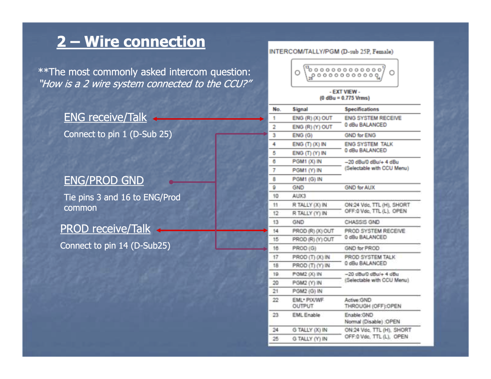
See photos above for pinouts for both the default 4-wire intercom connections as well as the optional 2-wire configuration. See also: https://clear-com.atlassian.net/wiki/spaces/SF/pages/256573574/Sony+CCU+Solutions